Mazda CX-5 Service & Repair Manual: Adaptive Front Lighting System (Afs) Off Switch Inspection
1. Disconnect the negative battery cable..
2. Remove the switch panel..
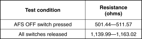
3. Verify that the resistance between AFS OFF switches B and C is as indicated in the table.
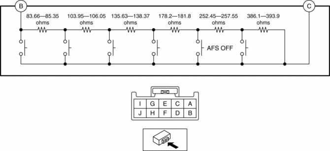
-
If the resistance can be verified as indicated in the table, go to the next step.
-
If not as indicated in the table, replace the cluster switch.
4. Apply battery positive voltage to AFS OFF switch terminal J, and connect terminal I to ground.
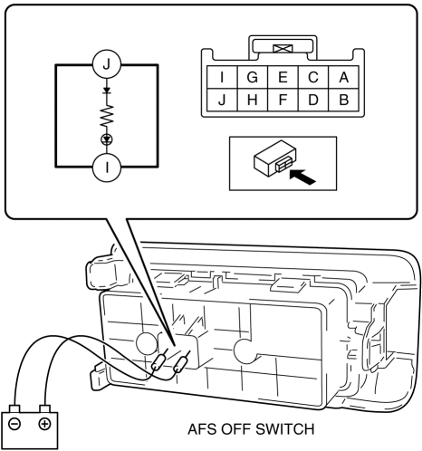
5. Verify that the LED illuminates.
-
If the LED does not illuminate, replace the cluster switch.

 Auto Light Sensor
Purpose
The auto light sensor detects the illumination level above and in front of
the vehicle and outputs it to the front body control module (FBCM).
Function
The auto-light se ...
Other materials:
Positive Crankcase Ventilation (PCV) System
Purpose, Outline
Prevents release of blow-by gas (unburnt gas) into the atmosphere.
The intake manifold vacuum introduces blow-by gas to the intake manifold
via the PCV valve and the ventilation hose.
System Diagram
Structure
The positive crankcase ventilation sys ...
Powertrain System Outline [Fw6 A EL, Fw6 Ax EL]
Outline
The powertrain consists of a 2-piece multi-plate clutch, 3-piece multi-plate
brake, a one-way clutch, and a 3-piece single-type planetary gear.
Construction
Component parts list
Component parts
Movement
Multi-plate clutch
...
Windshield Wiper System
Outline
Equipped with continuous (low/high), auto-stop, one-touch wiper, intermittent
wiper (without auto wiper system), auto wiper (with auto wiper system), and
synchronized washer and wiper operation.
The front body control module (FBCM) performs windshield wiper and washer
...
