Mazda CX-5 Service & Repair Manual: Antenna Feeder No.1 Removal/Installation
With audio system
1. Disconnect the negative battery cable..
2. Remove the following parts:
a. Side speaker grille (RH).
b. Tweeter (RH).
c. A-pillar trim.
d. Passenger-side front scuff plate.
e. Passenger-side front side trim.
f. Glove compartment.
g. Decoration panel.
h. Dashboard under cover.
i. Passenger-side lower panel.
j. Audio unit.
3. Remove clips A, B, C, D, E, and G.
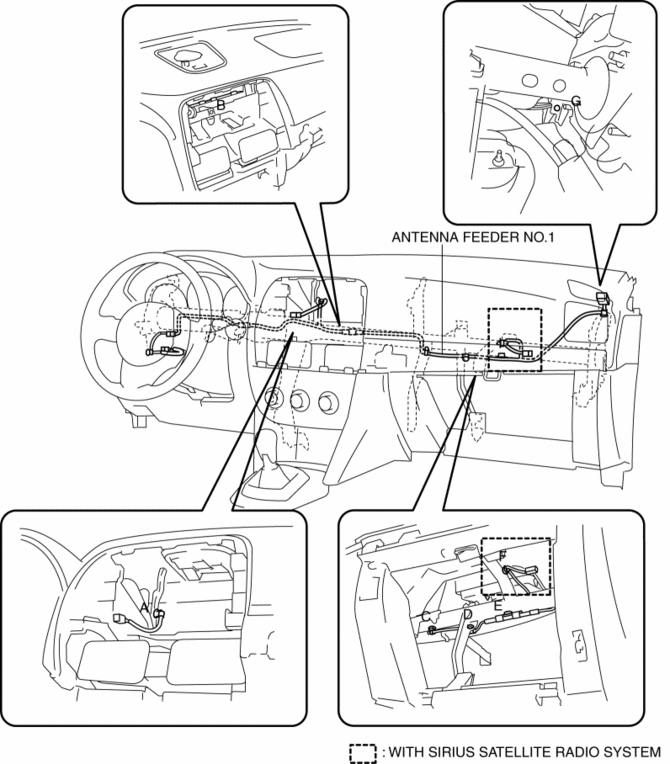
4. Disconnect the SIRIUS satellite radio unit connector. (with SIRIUS satellite radio system)
5. Remove the clip F. (with SIRIUS satellite radio system)
6. Remove antenna feeder No.1.
7. Install in the reverse order of removal.
With car-navigation system
1. Disconnect the negative battery cable..
2. Remove the following parts:
a. Center speaker grille.
b. Front center speaker (with Bose®)/front center speaker dummy (without Bose®).
c. GPS antenna.
d. Side speaker grille (RH).
e. Tweeter (RH).
f. A-pillar trim.
g. Front scuff plate.
h. Front side trim.
i. Car-navigation unit.
j. Switch panel.
k. Decoration panel.
l. Shift lever knob (MTX).
m. Front console box.
n. Shift panel.
o. Upper panel.
p. Rear console.
q. Side wall.
r. Front console.
s. Hood release lever.
t. Driver-side lower panel.
u. Glove compartment.
v. Dashboard under cover.
w. Passenger-side lower panel.
x. Audio unit.
3. Remove clips A, B, C, D, E, F, H, I, J, K, and L.
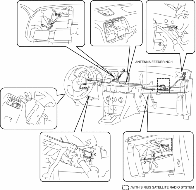
4. Disconnect the SIRIUS satellite radio unit connector. (with SIRIUS satellite radio system)
5. Remove the clip G. (with SIRIUS satellite radio system)
6. Remove antenna feeder No.1.
7. Install in the reverse order of removal.
 Antenna Feeder No.1 Inspection
With audio system
1. Disconnect the negative battery cable..
2. Remove the following parts:
a. A-pillar trim (RH).
b. Decoration panel.
c. Audio unit.
3. Disconnect antenna feeder No.2.
...
 Antenna Feeder No.2 Inspection
1. Disconnect the negative battery cable..
2. Remove the following parts:
a. A-pillar trim (RH).
b. Trunk board.
c. Trunk end trim (RH).
d. Rear scuff plate (RH).
e. Trunk side trim (RH). ...
Other materials:
Audio Set (Type A)
1 Power/Volume/Sound Controls
2 Operating the Radio
3 Operating the Compact Disc (CD) Player
4 How to use auxiliary jack/USB port
5 Error Indications
Power/Volume/Sound Controls
Power ON/OFF
Switch the ignition to ACC or ON. Press the power/volume dial to turn the audio
system on. Pre ...
Oil Pressure Switch [Fw6 A EL, Fw6 Ax EL]
Purpose/Function
The oil pressure switch detects the engagement pressures of the low clutch,
2-6 brake, R-3-5 brake, and the high clutch.
The oil pressure switch signal is used for automatic shift control, manual
shift control, TCC control, line pressure control, direct electric ...
Brake System/ABS Warning Light
Purpose/Function
The brake system/ABS warning light is built into the instrument cluster.
If a malfunction is detected in the system with the parking brake released,
the warning light illuminates to notify the driver.
Construction/Operation
When the DSC system and CAN l ...
