Mazda CX-5 Service & Repair Manual: Discharge Headlight System
Outline
-
The discharge headlight system utilizes a gas discharge type light to emit a white light resembling sunlight over a wide area. Also, use of the gas discharge type light realizes high efficiency, low power consumption lighting.
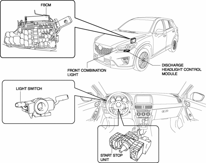
Structural View
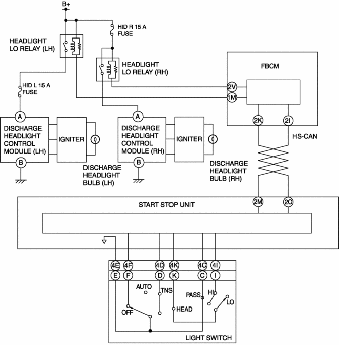
System Wiring Diagram
Operation
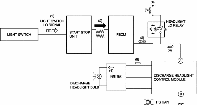
1. When the light switch is operated to the HEAD position, a light switch LO signal is input to the start stop unit.
2. The start stop unit sends the light switch LO signal to the front body control module (FBCM) as a CAN signal.
3. When the front body control module (FBCM) receives the light switch LO signal, it turns the headlight LO relay on.
4. When the headlight LO relay turns on, the igniter raises the DC voltage from the battery to approx. 25,000 V and outputs it to the discharge headlight bulb so that the xenon gas emits light.
5. When the discharge headlight bulb (xenon gas) emits light, the discharge headlight control module converts the DC voltage from the battery to AC voltage (approx. 42 V) and outputs it to the discharge headlight bulb to illuminate the bulb.
 Discharge Headlight Service Warnings
Discharge Headlight Service Warnings
When replacing a discharge headlight bulb, performing the servicing with
the negative battery cable connected or in a wet work area could result in elect ...
 Discharge Headlight System Inspection
WARNING:
Incorrect servicing of the discharge headlights could result in electrical
shock. Before servicing the discharge headlights, always refer to the service
warnings..
Termina ...
Other materials:
Controller Area Network (Can)
Outline
The DSC HU/CM sends and receives data to and from other modules via the CAN
system. Refer to MULTIPLEX COMMUNICATION SYSTEM for a detailed explanation of
the CAN system..
Data sent
Cruise control system-related information
DSC system-related information
...
Start Stop Unit Configuration (Using As Built Data)
NOTE:
If the configuration is performed using As-Built data, the set value of the
personalization function is reset to the initial value (condition when shipped
from factory). Verify the set value with the customer and perform the personalization
function setting after performing th ...
Interior Equipment (View B)
1 Audio control switches
2 SRS air bags
3 Cruise control switches
4 Navigation system (if equipped)
5 Audio system
6 Hazard warning flasher switch
7 Climate control system
8 Glove compartment
9 Rear window defroster switch
10 Accessory socket
11 MT shift lever
12 AT shift lever ...
