Mazda CX-5 Service & Repair Manual: Liftgate Light Removal/Installation
NOTE:
-
Fogging or condensation on the inside of the liftgate light may occur, however, it is a natural phenomenon occurring as a result of a temperature difference between the interior and exterior of the liftgate lights and has no effect on the light performance. Fogging or condensation will dissipate when the temperature inside the liftgate lights rises after illuminating the back-up lights and a period of time has elapsed.
1. Disconnect the negative battery cable..
2. Insert a tape-wrapped flathead screwdriver into the service hole in the position shown in the figure.
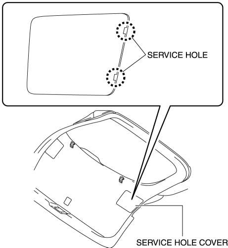
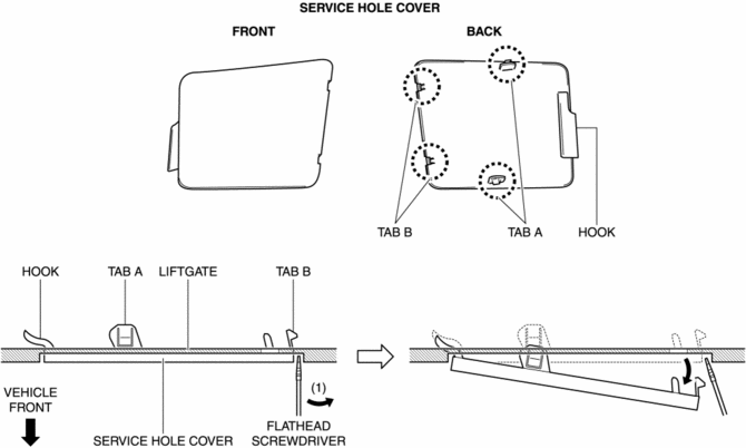
3. Move the flathead screwdriver in the direction of the arrow (1) shown in the figure, pull out the service hole cover from the liftgate, and detach the service hole cover tab A, B and liftgate.
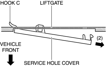
4. Pull out the service hole cover in the direction of the arrow (2) shown in the figure and pull out the service hole cover hook C from the liftgate.
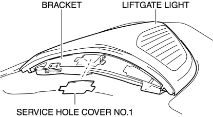
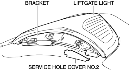
5. Remove the service hole cover.
6. Insert a flathead screwdriver into the service hole in the position shown in the figure.
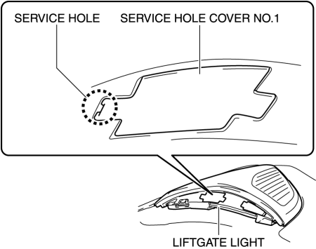
7. Move the flathead screwdriver in the direction of the arrow (3) shown in the figure, pull out the service hole cover No.1, and detach the service hole cover No.1 tab D from the bracket.
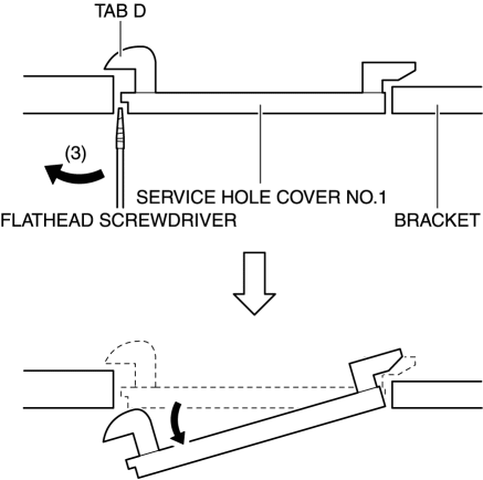
8. Remove the service hole cover No.1.
9. Insert a flathead screwdriver into the service hole in the position shown in the figure.
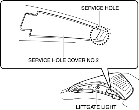
10. Move the flathead screwdriver in the direction of the arrow (4) shown in the figure, pull out the service hole cover No.2, and detach the service hole cover No.2 tab E from the bracket.
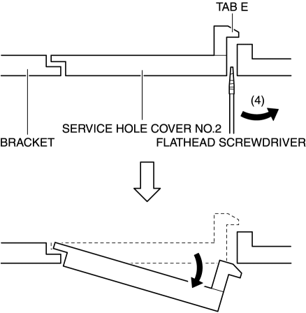
11. Remove the service hole cover No.2.
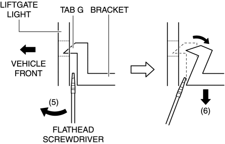
12. Insert the flathead screwdriver into the clearance between the bracket tab F and the liftgate light shown in the figure.
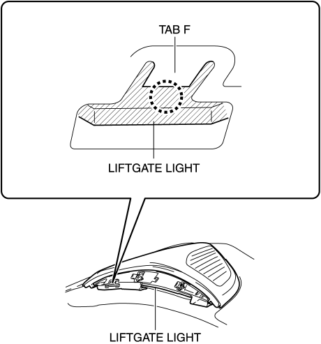
13. Move the flathead screwdriver in the direction of the arrow (5) shown in the figure, pull out the bracket in the direction of the arrow (6) shown in the figure while pressing the bracket tab, and detach the bracket tab G and liftgate light.
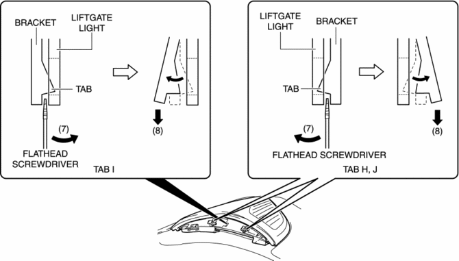
14. Insert the flathead screwdriver into the clearance between the bracket tab and the liftgate light shown in the figure.
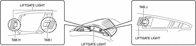
15. Move the flathead screwdriver in the direction of the arrow (7) shown in the figure, pull the bracket in the direction of the arrow (8) shown in the figure, and detach the bracket tab H, I, J and liftgate light.
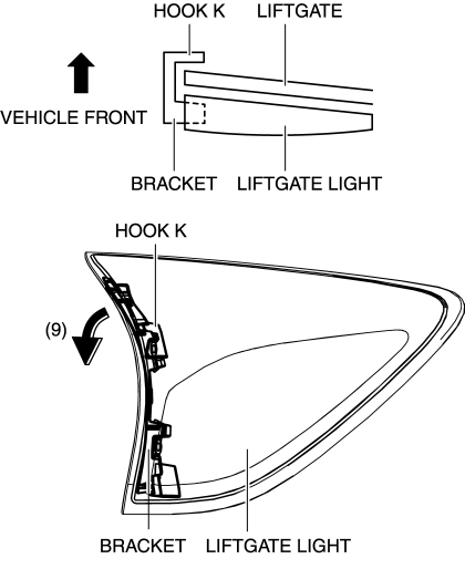
16. Move the bracket in the direction of arrow (9) shown in the figure to pull out hook K of the bracket from the liftgate.
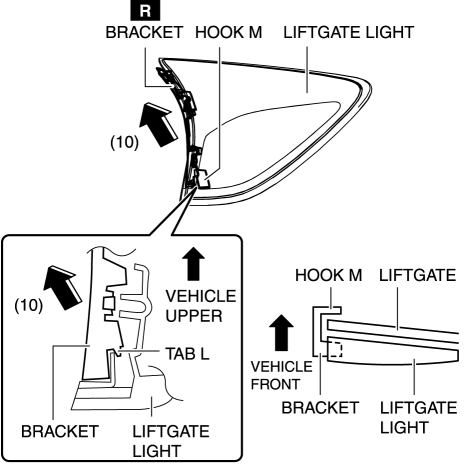
17. Move the bracket in the direction of arrow (10) shown in the figure to detach tab L of the bracket from the liftgate light, then pull out hook M of the bracket from the liftgate and remove the bracket.
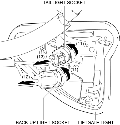
18. Rotate the socket in the direction of the arrow (11) shown in the figure and remove it from the liftgate light in the direction of the arrow (12) shown in the figure.
19. Remove the cap nut.
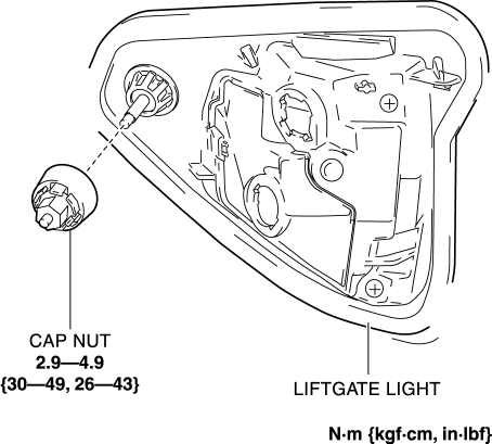
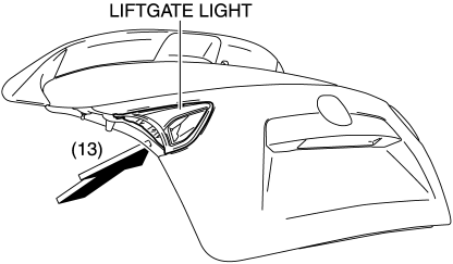
20. Push out the liftgate light in the direction of the arrow (13) shown in the figure and remove it from the liftgate.
CAUTION:
-
If the liftgate light is removed from the liftgate, the liftgate light may fall off and be damaged. When removing the liftgate light from the liftgate, hold the liftgate light on the lens side with a hand during the servicing.
21. Install in the reverse order of removal.
 Liftgate Light
Purpose
The liftgate lights are used to signal the following conditions to vehicles/people
at the rear.
Back-up lights: Signals that the vehicle is backing up.
Tailli ...
 Liftgate Lock Striker Removal/Installation
1. Remove the trunk end trim..
2. Remove the bolts, then remove the liftgate lock striker.
3. Install in the reverse order of removal.
4. Adjust the liftgate.. ...
Other materials:
Wheel Hub, Steering Knuckle Inspection
Wheel Bearing Excessive Play Inspection
1. Install the magnetic base and dial gauge as shown in the figure and measure
the wheel bearing axial excessive play.
If it exceeds the maximum specification, replace the wheel hub bearing.
Front wheel bearing maximum play
0 ...
Instrument Cluster Removal/Installation
CAUTION:
If configuration is not performed when the instrument cluster is replaced
with a new one, the vehicle specification information is not stored in the instrument
cluster and the system will not operate normally.
When performing configuration, it is necessary to read the ...
Liftgate Latch And Lock Actuator Removal/Installation
1. Disconnect the negative battery cable..
2. Remove the following parts:
a. Liftgate upper trim.
b. Liftgate side trim.
c. Liftgate lower trim.
3. Disconnect the connector.
4. Remove the bolts.
5. Remove the liftgate latch and lock actuator from the liftgate.
6. Install in t ...
