Mazda CX-5 Service & Repair Manual: Relay Inspection
Relay Type
|
Connector type |
Part name |
|
Type A |
|
|
Type B |
|
|
Type C |
Blower relay |
|
Type D |
|
|
Type E |
Starter relay |
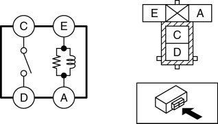
Type A
1. Remove the relay..
2. Verify the continuity between relay terminals E and A.
-
If it can be verified, go to the next step.
-
If it cannot be verified, replace the relay..
3. Apply battery voltage to relay terminal E, and connect terminal A to ground.
4. Verify the continuity between relay terminals C and D.
-
If it cannot be verified, replace the relay..
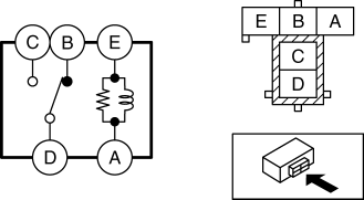
Type B
1. Remove the relay..
2. Verify the continuity between relay terminals E and A.
-
If it can be verified, go to the next step.
-
If it cannot be verified, replace the relay..
3. Verify the continuity between the relay terminals B and D.
-
If it can be verified, go to the next step.
-
If it cannot be verified, replace the relay..
4. Apply battery voltage to relay terminal E, and connect terminal A to ground.
5. Verify the continuity between relay terminals C and D.
-
If it cannot be verified, replace the relay..
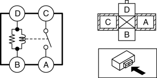
Type C
1. Remove the relay..
2. Verify the continuity between the relay terminals D and B.
-
If it can be verified, go to the next step.
-
If it cannot be verified, replace the relay..
3. Apply battery voltage to relay terminal D, and connect terminal B to ground.
4. Verify the continuity between relay terminals C and A.
-
If it cannot be verified, replace the relay..
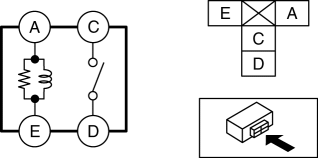
Type D
1. Remove the relay..
2. Verify the continuity between relay terminals A and E.

-
If it can be verified, go to the next step.
-
If it cannot be verified, replace the relay..
3. Apply battery voltage to relay terminal A, and connect terminal E to ground.
4. Verify the continuity between relay terminals D and C.
-
If it cannot be verified, replace the relay..
Type E
1. Remove the relay..
2. Verify the continuity between relay terminals A and E.
-
If it can be verified, go to the next step.
-
If it cannot be verified, replace the relay..
3. Apply battery voltage to relay terminal A, and connect terminal E to ground.
4. Verify the continuity between relay terminals C and D.
-
If it cannot be verified, replace the relay..
 Main Relay [Skyactiv G 2.0]
Purpose/Function
Supplies power to each part.
Supplies battery voltage to each part based on the signals from the PCM even
though the ignition is switched on or off.
Constructi ...

Other materials:
Abbreviations
AAS
Active Adaptive Shift
ABS
Antilock Brake System
ABDC
After Bottom Dead Center
ACC
Accessories
AFS
Adaptive Front Lighting System
ALC
...
Cruise Set Indicator Light (Green)
Purpose/Function
Illuminates during the cruise control system operation to inform the driver
that the cruise control system is operating.
Construction
Built into the instrument cluster.
Operation
Illuminates during the cruise control system operation.
...
Front Drive Shaft (Double Offset Joint) Disassembly/Assembly
1. Disassemble in the order indicated in the table.
2. Assemble in the reverse order of disassembly.
1
Boot band (transaxle side)
(See FRONT DRIVE SHAFT (TRIPOD JOINT) DISASSEMBLY/ASSEMBLY.)
2
Clip
(See Clip Disassembly Note.)
...
