Mazda CX-5 Service & Repair Manual: Tcs Control
Outline
-
The TCS control actuates torque reduction through engine control, as well as using brake control to control traction.
NOTE:
-
Engine control: Engine output is lowered by fuel cut and ignition timing control to reduce the traction, preventing driving wheel slip.
-
Brake control: Brake fluid pressure from the hydraulic unit (HU) to the driving wheel that is slipping is increased, operating the brake and preventing driving wheel slip.
Features
-
The left and right wheels are controlled at the same time by engine control. Therefore, when the road surface friction coefficients differ between the left and right wheels, proper torque reduction cannot be performed separately for each wheel. When this occurs, torque reduction is performed by independent left and right wheel brake control, providing more stable vehicle control.
-
The TCS OFF switch allows the driver to optionally enable/disable the TCS control at the driver's discretion.
-
When both driving wheels are stuck, traction control according to the driver's operation can be performed by inhibiting the TCS control.
-
The TCS control returns to normal operation automatically at the next ignition cycle.
Construction
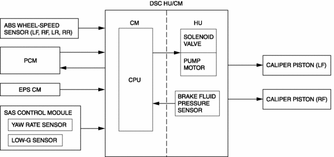
Block Diagram
Operation
-
TCS control detects driving wheel spin based on the signals listed below, sends torque reduction request signals to the PCM, and also controls the solenoid valves and pump motor in the DSC HU/CM.
-
Vehicle wheel speed signals from the font and rear ABS wheel-speed sensors
-
Engine torque signal from the PCM
-
Steering angle signal from the EPS CM
-
Yaw rate and lateral-G signals from the SAS control module
-
Fluid pressure signal from the brake fluid pressure sensor (built into the DSC HU/CM)
 Precaution [Dynamic Stability Control (DSC)]
1. The ABS warning light and/or brake system warning light and/or TCS/DSC indicator
light and/or TCS OFF indicator light illuminate even when the system is normal.
Warning ...
 Tcs Off Switch Inspection
1. Remove the TCS OFF switch..
2. Verify that the resistance between the TCS OFF switch terminals B and C is
as indicated in the table.
If not as indicated in the table, replace the TCS OF ...
Other materials:
High Pressure Fuel Pump Control
Outline
Changes the fuel pressure applied to the fuel injector according to engine
operation conditions to improve engine output and startability.
The PCM determines the fuel pressure value corresponding to the engine operation
conditions based on the each input signal, and driv ...
Rear Bumper Removal/Installation
CAUTION:
Affix the protective tape to the position (body side) shown in the figure.
1. Disconnect the negative battery cable..
2. Remove the rear combination light..
3. Remove fasteners A.
4. Pull the rear over fender in the direction of the arrow shown in the figure
...
Ignition System [Skyactiv G 2.0]
Outline
A direct ignition coil for independent ignition control has been adopted.
An ignition coil built-into the ion sensor has been adopted.
An iridium spark plug has been adopted.
Structural View
Structure
Consists of the following parts:
...
