Mazda CX-5 Service & Repair Manual: Tie Rod End Replacement
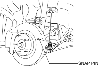
1. Remove the snap pin.
2. Loosen the tie-rod end locknut.
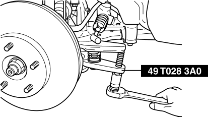
3. Detach the tie-rod end from the steering knuckle using the SST
.
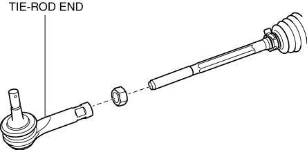
4. Remove the tie-rod end locknut.
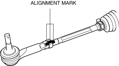
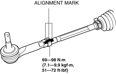
5. Place alignment marks as shown in the figure for proper installation.
6. Remove the tie-rod end.
7. Align the alignment marks made before removing the tie-rod end, and then install a new tie-rod end to the tie rod.
-
If there are no alignment marks, go to the following procedure.
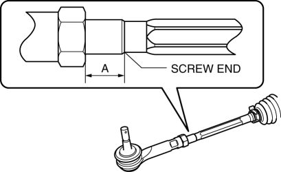
8. Adjust dimension A shown in the figure to the standard, and assemble.
-
Standard Dimension A
-
10.1—23.1 mm {0.398—0.909 in}
9. Install the tie-rod end to the steering knuckle.
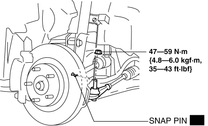
10. Install a new snap pin.
11. After installation, inspect the front wheel alignment and adjust it if necessary..
 Tie Rod End Inspection
1. Inspect the tie-rod end for damage and the boot for cracks.
If there is any malfunction, replace the tie-rod end.
2. Inspect for excessive play.
If there is any malfunction, ...
 Tie Rod Inspection
1. Inspect for bending and damage.
If there is any malfunction, replace the tie rod.
2. Inspect for excessive play.
If there is any malfunction, replace the tie rod.
3. Swi ...
Other materials:
Manifold Absolute Pressure (Map) Sensor/Intake Air Temperature (Iat) Sensor
No.2 Removal/Installation
NOTE:
Because the IAT sensor No.2 is integrated in the MAP sensor, replacing the
IAT sensor No.2 includes replacement of the MAP sensor/IAT sensor No.2.
1. Disconnect the negative battery cable..
2. Disconnect the MAP sensor/IAT sensor No.2 connector.
3. Remove the MAP sensor/IA ...
Automatic Transaxle Outline [Fw6 A EL, Fw6 Ax EL]
Outline
Contribution to low fuel economy
Wide TCC range
Clutch/brake resistance reduction
Realized direct feel and quick shifting
Oil passage resistance reduction and improved clutch/brake response
b ...
Rear Differential Assembly
WARNING:
The engine stand is equipped with a self-lock mechanism, however, if the
rear differential is in a tilted condition, the self-lock mechanism could become
inoperative. If the rear differential unexpectedly rotates it could cause injury,
therefore do not maintain the rear dif ...
