Mazda CX-5 Service & Repair Manual: Rear Fender Panel Removal [Panel Replacement]
Symbol Mark

Removal Procedure
CAUTION:
-
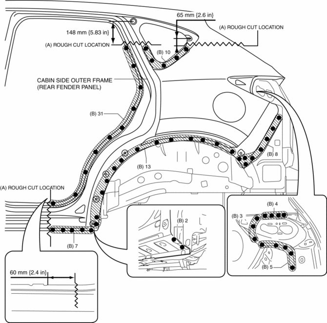
Avoid cutting with a blowtorch or similar tools as the insulator (shaded area) is flammable.

1. Rough cut the 3 locations indicated by (A) shown in the figure.
2. Drill the 90 locations indicated by (B) shown in the figure.


3. Remove the cabin side outer frame (rear fender panel).
 Rear Fender Panel Installation [Panel Replacement]
Symbol Mark
Installation Procedure
1. When installing new parts, measure and adjust the body as necessary to conform
with standard dimensions.
2. Drill holes for the plug welding before inst ...
 Rear Over Fender Removal/Installation
1. Remove fasteners A.
2. Pull the rear over fender in the direction of the arrow while removing clips
B.
3. Install in the reverse order of removal. ...
Other materials:
Turn And Hazard Indicator Alarm
Purpose
The turn and hazard indicator alarm notifies the driver that a turn light
or the hazard warning lights are flashing.
Function
When the instrument cluster receives the turn signal/hazard warning indicator
light illumination request signal sent from the front body con ...
Engine Oil Solenoid Valve
Purpose, Function
The engine oil solenoid valve switches the hydraulic transmission passage
in accordance with the driving conditions and the oil pump drive resistance
is reduced by controlling oil pump discharging pressure in two steps.
Construction
The engine oil solenoid ...
Start Stop Unit Configuration (Using As Built Data)
NOTE:
If the configuration is performed using As-Built data, the set value of the
personalization function is reset to the initial value (condition when shipped
from factory). Verify the set value with the customer and perform the personalization
function setting after performing th ...
