Mazda CX-5 Service & Repair Manual: Windshield Wiper System
Outline
-
Equipped with continuous (low/high), auto-stop, one-touch wiper, intermittent wiper (without auto wiper system), auto wiper (with auto wiper system), and synchronized washer and wiper operation.
-
The front body control module (FBCM) performs windshield wiper and washer system fail-safe..
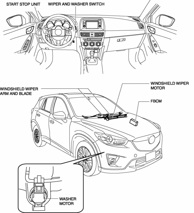
Structural View

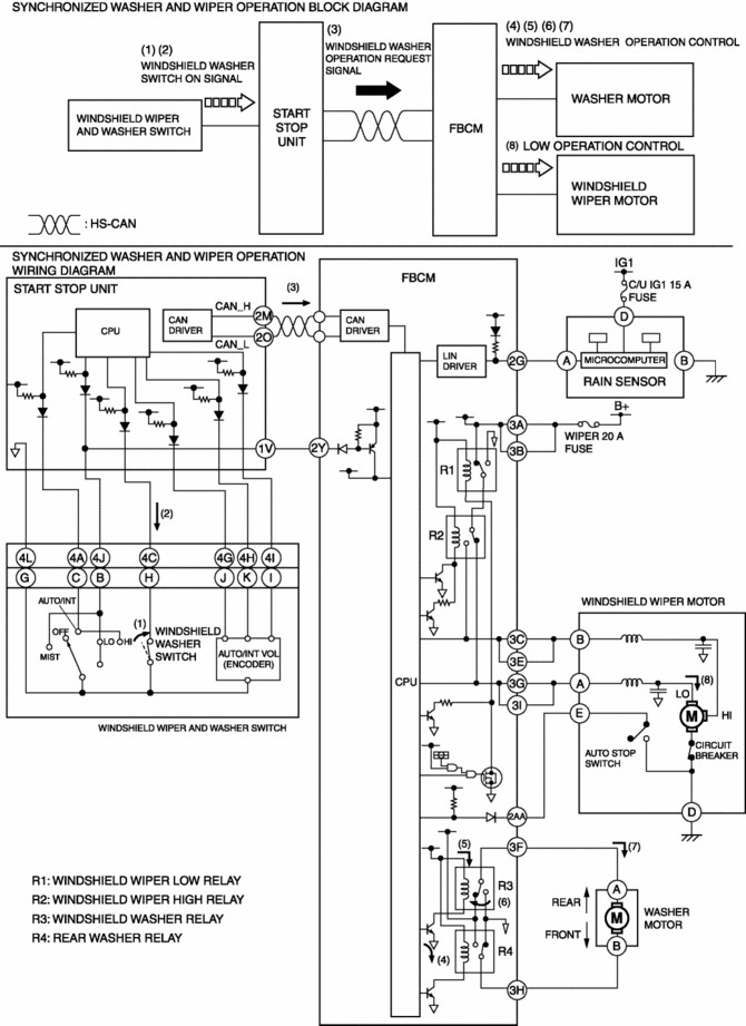
System Wiring Diagram

Operation
Continuous low operation
1. When the wiper and washer switch is moved to the LO position with the ignition switched ON (engine off or on) (1), the start stop unit detects a windshield wiper switch signal (LO).(2)
2. When the start stop unit detects the windshield wiper switch signal (LO), it send a windshield wiper switch position signal (LO) to the front body control module (FBCM) as a CAN signal.(3)
3. When the front body control module (FBCM) receives the windshield wiper switch position signal (LO), it supplies the base current from the internal CPU to transistor A (4), and collector current flows from the internal power supply (5), turning the windshield wiper low relay on. (6)
4. When the windshield wiper low relay is turned on, current flows from the battery to the windshield wiper motor and the windshield wipers operate continuously at low speed.(7)

Continuous high operation
1. When the wiper and washer switch is moved to the HI position with the ignition switched ON (engine off or on) (1), the start stop unit detects a windshield wiper switch signal (HI).(2)
2. When the start stop unit detects a windshield wiper switch signal (HI), it send a windshield wiper switch position signal (HI) to the front body control module (FBCM) as a CAN signal.(3)
3. When the front body control module (FBCM) receives the windshield wiper switch position signal (HI), it supplies the base current from the internal CPU to transistors A and B (4), and collector current flows from the internal power supply (5), turning the windshield wiper low relay and windshield wiper high relay on.(6)
4. When the windshield wiper low relay and windshield wiper high relay are turned on, current flows from the battery to the windshield wiper motor and the windshield wipers operate continuously at high speed.(7)

Auto-stop operation
1. During intermittent operation, or when the wiper and washer switch is moved to the OFF position (1), the auto stop switch inside the windshield wiper motor turns on when the windshield wipers move to the park position.(2)
2. When the front body control module (FBCM) detects that the auto stop switch is on, it stops the base current to the transistor (3) and turns off the windshield wiper low relay, and the windshield wipers stop at the park position.

One-touch wiper operation
1. When the wiper and washer switch is moved up with the ignition switched ON (engine off or on) (1), the start stop unit detects a windshield wiper switch signal (LO).(2)
2. When the start stop unit detects a windshield wiper switch signal (LO), it send a windshield wiper switch position signal (LO) to the front body control module (FBCM) as a CAN signal.(3)
3. When the front body control module (FBCM) receives the windshield wiper switch position signal (LO), it supplies the base current from the internal CPU to transistor A (4), and collector current flows from the internal power supply (5), turning the windshield wiper low relay on.(6)
4. When the windshield wiper low relay is turned on, current flows from the battery to the windshield wiper motor and the windshield wipers operate at low speed.(7)

Intermittent wiper operation (without auto wiper system)
1. When the wiper and washer switch is moved to the INT position with the ignition switched ON (engine off or on) (1), the start stop unit detects a windshield wiper switch signal (INT).(2)
2. When the start stop unit detects a windshield wiper switch signal (INT), it send a windshield wiper switch position signal (INT) and an INT volume signal to the front body control module (FBCM) as CAN signals.(3)
3. When the front body control module (FBCM) receives the windshield wiper switch position signal (INT), it supplies the base current from the internal CPU to transistor A (4), and collector current flows from the internal power supply (5), turning the windshield wiper low relay on.(6)
4. When the windshield wiper low relay is turned on, current flows from the battery to the windshield wiper motor and the windshield wipers operate continuously at low speed.(7)
5. The windshield wipers stop at the park position due to the auto stop operation, and after a certain period of time has elapsed, which was calculated based on the INT volume signal, the front body control module (FBCM) operates the windshield wipers at a low speed. By repeating this, the windshield wipers operate intermittently.(8)

Auto wiper operation (with auto wiper system)
-
Refer to AUTO WIPER SYSTEM for a detailed explanation of the auto wiper operation..
Synchronized washer and wiper operation
1. When the windshield washer switch is turned on with the ignition switched ON (engine off or on) and the windshield wipers not operated (1), the start stop unit detects a windshield washer switch ON signal.(2)
2. When the start stop unit detects a windshield washer switch ON signal, it send a windshield washer operation request signal to the front body control module (FBCM) as a CAN signal.(3)
3. When the front body control module (FBCM) receives the windshield washer operation request signal, it supplies the base current from the internal CPU to transistor C (4), and collector current flows from the internal power supply (5), turning the windshield washer relay on.(6)
4. When the windshield washer relay is turned on, current flows from the power supply inside the front body control module (FBCM) to the washer motor and the washer motor operates, and washer fluid is sprayed from the front washer nozzles.(7)
5. When the front body control module (FBCM) receives the windshield washer operation request signal for a certain period of time, it operates the windshield wipers at low speed.(8)
6. When the windshield washer switch is turned off, the operation stops after the windshield wipers operate two times.
NOTE:
-
If the windshield washer switch is turned on while the windshield wipers are operating, windshield wiper operation is continued and the windshield washer operation, from (3) to (7), is performed.

LO/HI detection function
-
The LO/HI detection function is used in the fail-safe function during a system malfunction.
-
The front body control module (FBCM) detects that the wiper and washer switch is in the LO or HI position and monitors it.

 Windshield Wiper Motor Inspection
1. Disconnect the negative battery cable..
2. Remove the following parts:
a. Windshield wiper arm and blade.
b. Cowl grille.
Windshield Wiper Motor Inspection
1. Apply battery positive voltag ...
 Wiper Bracket Removal [Panel Replacement]
Symbol Mark
Installation Procedure
1. When installing new parts, measure and adjust the body as necessary to conform
with standard dimensions.
2. Drill holes for the plug welding before inst ...
Other materials:
Auto Dimming Mirror Removal/Installation
1. Disconnect the negative battery cable..
2. Remove the screw B.
3. Remove the auto-dimming mirror in the direction of arrow (1) shown in the
figure.
4. Detach tabs while push the cover No.2 in the direction of the arrow (2) shown
in the figure, then remove the cover No.2 in the d ...
Instrument Cluster Configuration (Using Read/Write Function)
NOTE:
When performing configuration, it is necessary to read the vehicle specification
information from the instrument cluster before replacing it. Connect the M-MDS
to the vehicle and perform vehicle identification before removing the instrument
cluster. The vehicle specification i ...
Electrical Fan Control
Outline
Through cooling of the radiator and condenser by operation of the cooling
fan according to vehicle conditions, engine reliability and cooling performance
have been improved.
Block Diagram
Operation
The PCM determines the demand airflow volume by the following c ...
