
Mazda CX-5 Service & Repair Manual: Pressure Sensor Removal/Installation [Two Step Deployment Control System]
WARNING:
-
Handling the pressure sensor improperly can accidentally operate (deploy) the air bag module, which may seriously injure you. Read the air bag system service warnings and cautions before handling the pressure sensor..
1. Switch the ignition to off.
2. Disconnect the negative battery cable and wait for 1 min or more
..
3. Remove the inner garnish..
4. Remove the front door trim..
5. Remove the bolts.
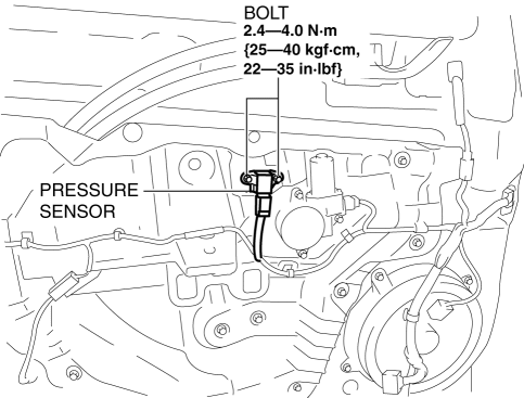
6. Remove the pressure sensor.
7. Disconnect the connector from the pressure sensor by pressing the connector tab and pulling out the lock lever in the direction of the arrow.

-
When connecting the pressure sensor connector, insert the lock lever (connector disconnection prevention lever) completely.
8. Install in the reverse order of removal.
9. Switch the ignition ON (engine off or on).
10. Verify that the air bag system warning light illuminates for approx. 6 s
and goes out.
-
If the air bag system warning light does not operate normally, refer to the on-board diagnostic system (air bag system) and perform inspection of the system..
 Pre Tensioner Seat Belt [Two Step Deployment Control System]
Purpose
The pre-tensioner seat belt retracts and tightens the seat belt webbing to
protect the front passengers during a collision.
Function
The pre-tensioner seat belts operate ...
 Pressure Sensor [Two Step Deployment Control System]
Purpose
The pressure sensor determines at an earlier stage whether to detonate the
air bag on the side of the vehicle (around front door) receiving an impact.
This is for improved accurac ...
Other materials:
Oil Cooler [Fw6 A EL, Fw6 Ax EL]
Purpose/Function
The oil cooler constantly maintains maximum ATF performance in the transaxle
by maintaining an optimum ATF temperature which has the effect of achieving
reduced fuel consumption.
Construction/Operation
The oil cooler performs the following operations accord ...
Fuses
Your vehicle's electrical system is protected by fuses.
If any lights, accessories, or controls do not work, inspect the appropriate
circuit protector. If a fuse has blown, the inside element will be melted.
If the same fuse blows again, avoid using that system and consult an Authorized
Ma ...
Parking Brake Lever Removal/Installation
1. Remove the front console box..
2. Remove the shift lever knob. (MTX).
3. Remove the shift panel..
4. Remove the upper panel..
5. Remove in the order indicated in the table.
6. Install in the reverse order of removal.
7. After installation, inspect the parking brake lever stroke..
...
