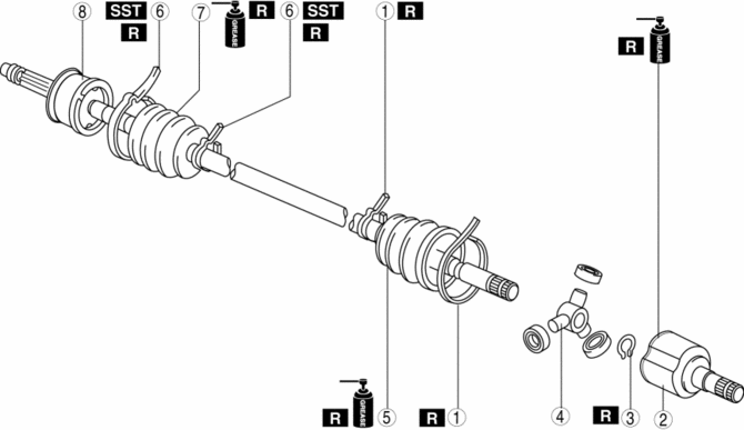
Mazda CX-5 Service & Repair Manual: Rear Drive Shaft Disassembly/Assembly
1. Disassemble in the order indicated in the table.
2. Assemble in the reverse order of disassembly.
|
1 |
Boot band (differential side) (See Boot Band (Differential Side) Disassembly Note.) (See Boot Band (Differential Side) Assembly Note.) |
|
2 |
Outer ring (See Outer Ring Disassembly Note.) (See Outer Ring Assembly Note) |
|
3 |
Snap ring (See Snap Ring, Tripod Joint Disassembly Note.) (See Boot Band (Differential Side) Assembly Note.) |
|
4 |
Tripod joint (See Snap Ring, Tripod Joint Disassembly Note.) (See Boot Band (Differential Side) Assembly Note.) |
|
5 |
Boot (See Boot Disassembly Note.) (See Boot Assembly Note.) |
|
6 |
Boot band (wheel side) (See Boot Band (Wheel Side) Disassembly Note.) (See Boot Band (Wheel Side) Assembly Note.) |
|
7 |
Boot (See Boot Disassembly Note.) (See Boot Assembly Note.) |
|
8 |
Shaft and ball joint component |
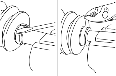
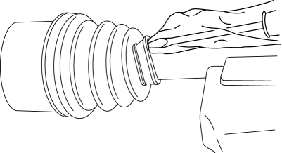
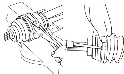
Boot Band (Differential Side) Disassembly Note
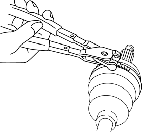
1. Pry up the boot band at the points indicated in the figure using pliers and remove the band.
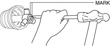
Outer Ring Disassembly Note
1. Mark the outer ring and the shaft for proper assembly.
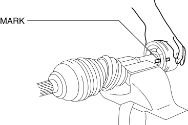
2. Remove the outer ring
Snap Ring, Tripod Joint Disassembly Note
1. Place an alignment mark on the shaft and tripod joint.
2. Remove the snap ring using snap ring pliers.
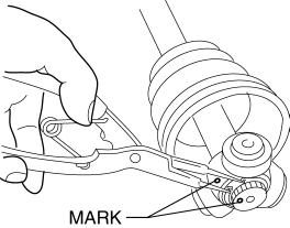
3. Remove the tripod joint from the shaft.
CAUTION:
-
Do not try to remove the tripod joint by hitting it with a hammer. The tripod joint could be damaged.
Boot Disassembly Note
NOTE:
-
Remove the wheel side boot only if there is any malfunction.
1. Wrap the shaft splines with tape.
2. Remove the boot.
Boot Band (Wheel Side) Disassembly Note
NOTE:
-
Remove the boot band only if there is a malfunction.
1. Remove the boot band using end clamp pliers.
Boot Assembly Note
NOTE:
-
The boot shapes on the wheel side and the differential side are different. Do not install the wrong boot by mistake.
1. Fill the inside of the new dust boot (wheel side) with grease.
NOTE:
-
Do not touch the grease with your hand. Apply it from the tube to prevent foreign matter from entering the boot.
-
Grease amount
-
40—60 g {1.5—2.1 oz}
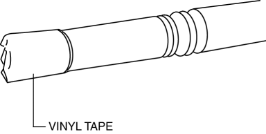
2. Install the boot with the drive shaft spline still wrapped with vinyl tape.
3. Remove the vinyl tape.
Boot Band (Wheel Side) Assembly Note
Boot band (small diameter side)
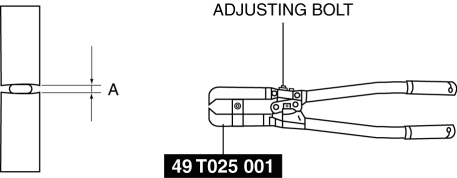
1. Adjust clearance A by turning the adjusting bolt of the SST
.
-
Clearance A
-
2.9 mm {0.11 in}
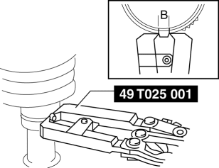
2. Crimp the wheel side small boot band using the SST
. Verify that clearance B is within the specification.
-
If clearance B is more than the specification, reduce clearance A of the SST
and crimp the boot again.
-
If clearance B is less than the specification, replace the boot band, increase clearance A of the SST
, and crimp the new boot.
-
Clearance B
-
2.4—2.8 mm {0.10—0.11 in}
3. Verify that the boot band does not protrude from the boot band installation area.
-
If it does, replace the boot band and repeat Steps 2 and 3.
Boot band (Large diameter side)
1. Adjust clearance C by turning the adjusting bolt of the SST
.
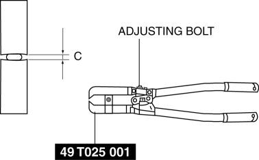
-
Clearance C
-
3.2 mm {0.13 in}
2. Crimp the wheel side small boot band using the SST
. Verify that clearance D is within the specification.
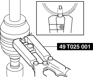
-
If clearance B is more than the specification, reduce clearance C of the SST
and crimp the boot again.
-
If clearance B is less than the specification, replace the boot band, increase clearance C of the SST
, and crimp the new boot.
-
Clearance D
-
2.4—2.8 mm {0.10—0.11 in}
3. Verify that the boot band does not protrude from the boot band installation area.
-
If it does, replace the boot band and repeat Steps 2 and 3.
Tripod Joint, Snap Ring Assembly Note
1. While aligning the marks on the shaft and the tripod joint, insert the tripod joint using a bar and a hammer.
2. Insert a new snap ring using snap ring pliers.
3. Verify that the snap ring is engaged correctly in the groove of the shaft.
Outer Ring Assembly Note
1. Fill the outer ring and boot (transaxle side) with the specified grease.
NOTE:
-
Do not touch the grease with your hand. Apply it from the tube to prevent foreign matter from entering the boot.
-
Grease amount
-
70—90 g {2.5—3.1 oz}
2. Assemble the outer ring.
3. Set the drive shaft to the standard length.
-
Rear drive shaft standard length
-
LH: 836.8—842.0 mm {32.95—33.14 in}
-
RH: 874.8—880.0 mm {34.45—34.64 in}
4. Release any trapped air from the boots by carefully lifting up the small end of each boot with a cloth wrapped screwdriver.
NOTE:
-
Verify that there is no grease leak while being careful not to damage the boot.
-
If the boot is damaged, it may not be possible to perform the full-length adjustment of the drive shaft.
5. Verify that the drive shaft length is within the specification under atmospheric pressure inside the boot.
-
If not within the specification, repeat from Step 3.
Boot Band (Differential Side) Assembly Note
1. Fold the band in the direction opposite to the forward revolving direction of the drive shaft and use pliers to pull it tight.
 Rear Drive Shaft
Purpose, Function
Engine noise and vibration have been reduced due to adoption of a bell joint
on the wheel side of the constant velocity joint.
A low noise and vibration double offs ...
 Rear Drive Shaft Inspection
1. Inspect each connecting part for looseness.
Tighten or replace parts if necessary.
2. Inspect the dust boot on the drive shaft for cracks, damage, leaking grease,
and looseness in t ...
Other materials:
Accelerator Pedal Position (App) Sensor Inspection
Voltage Inspection
NOTE:
Because the APP sensor is integrated in the accelerator pedal, replacing
the APP sensor includes replacement of the accelerator pedal.
1. Connect the M-MDS to the DLC?2.
2. Switch the ignition ON (engine off or on).
3. Verify that the APP sensor output ...
Hood Removal/Installation
WARNING:
Removing the hood without supporting it could cause the hood to fall and
cause serious injury. Always perform the procedure with at least another person
to prevent the hood from falling.
1. Disconnect the negative battery cable..
2. Remove the following parts:
a. Fro ...
Oil Pressure Switch Inspection
1. Switch the ignition ON (engine off) and verify that the oil pressure warning
light is illuminated.
2. Start the engine and verify that the oil pressure warning light turns off.
If the oil pressure warning light is not illuminated or remains illuminated,
inspect the wiring harness ...
